In this project I developed and built a electromagnetically driven spinning top. The image on the right shows a spinning top with 10 cylindrical NdFeB magnets placed in a 3D printed form and the electromagnetic driver (single coil accelerator) that is powered via USB cable. The spinning top can reach high speeds up to around 70 revolutions per second. Here the parameters of the NdFeB (N52) magnets are:
- height (h): 5 mm
- diameter (D): 10 mm
- remanence flux (Br): 1.42-1.47 Tesla
The component costs are estimated at 25$.
If you’d like to download the STL files for 3D printing, you can access them here:
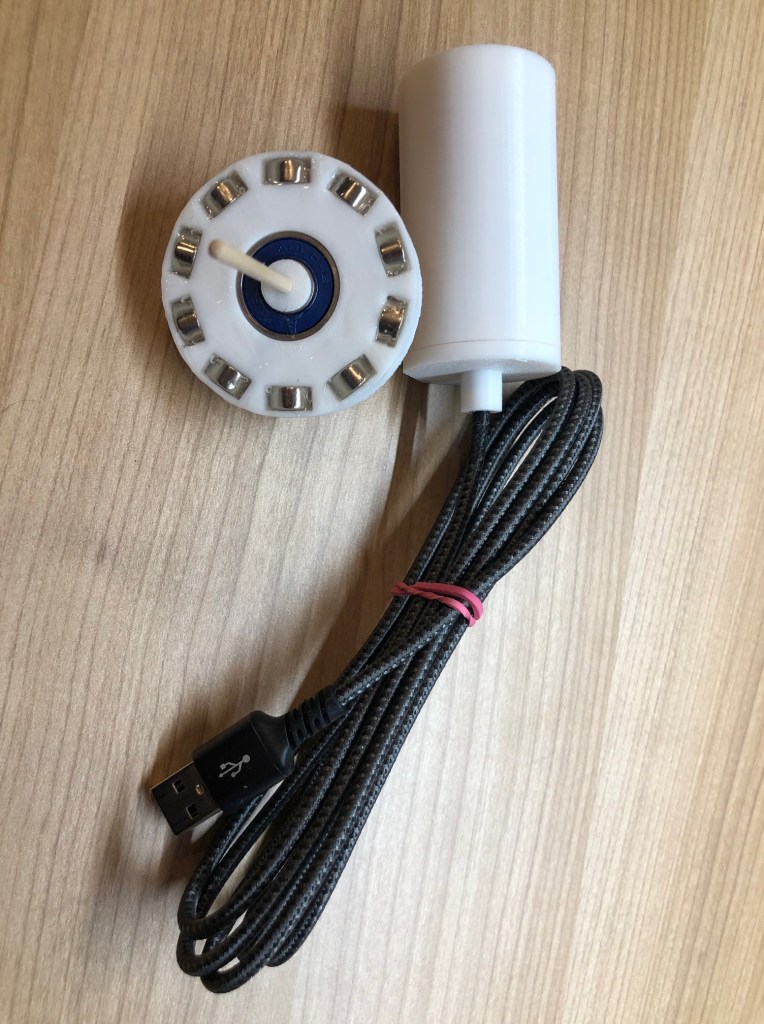
The first prototype in this project was built with a fidget spinner and a portable driver including a 9V block battery. The final driver is equal to the first prototype, but the power supply is changed to USB such that one does not need a battery.
This is a demonstration of the phenomenon known as precession motion in a spinning top. During precession, the symmetry axis of the spinning top rotates around a fixed vertical axis.
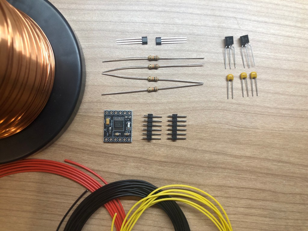
Components for the accelerator:
- 4 x 10k Resistors
- 3 x 10nF Capacitors
- 2 x BC337 Transistors
- 2x TLE 4905L Unipolar Hallsensors
- 1 x DRV8833 H-Bridge chip
- 1 x coated copper wire with diameter 0.5 mm
- 1 x PCB board
- 1 x 3D printed coil holder
- 1 x 3D printed case
- 1 x USB cable for 5V power supply
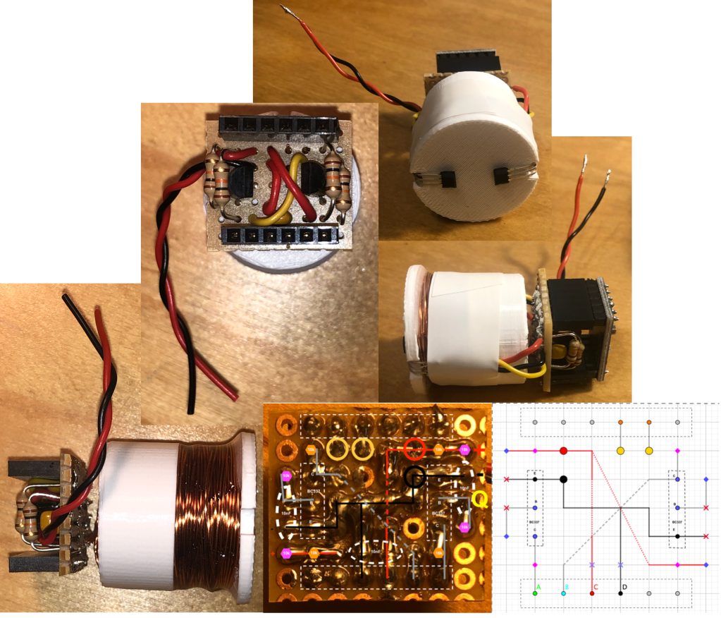
The accelerator features a single coil driven by an H-bridge chip (DRV8833), which is controlled by two Hall sensors (TLE4905L). These sensors detect the position of the magnets on the spinning top, enabling the accelerator to generate a self-regulated AC current signal. The system is powered via a 5V USB cable, with a recommended power supply capable of delivering electric currents greater than 3 Amperes.
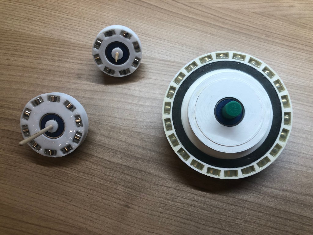
I designed several spinning top geometries to study their different dynamical behaviors. The large spinning top demonstrates high stability due to its greater inertia and higher kinetic energy, while the smaller tops are less stable at low speeds but accelerate more quickly.
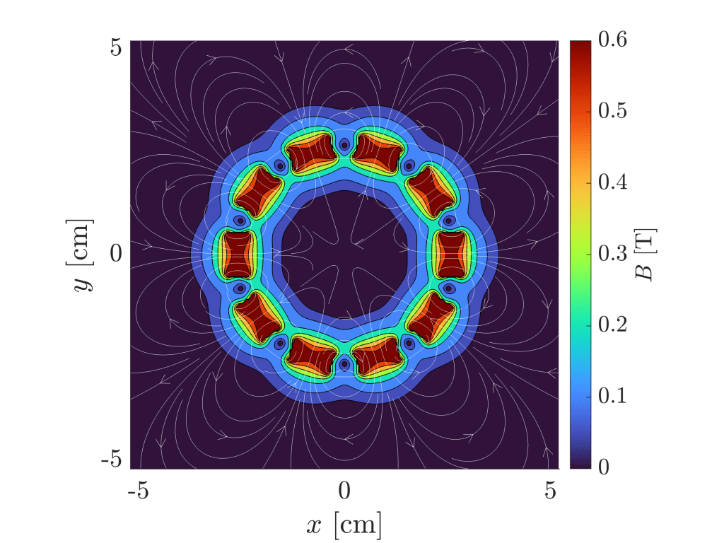
The magnets are arranged in an antiparallel configuration, with their magnetization oriented opposite to that of their neighboring magnets. This arrangement was chosen to maximize the magnetic field gradients, ensuring a more efficient interaction with the electromagnetic driver while minimizing stray fields. In the large spinning top, I added a ring of glued iron filings, which further reduce stray fields and allowing a higher accelerating torque.
This is a computed example for the magnetic flux density in the plane perpendicular to the symmetry axis of the spinning top. In this example we have 10 NdFeB magnets with a remanence flux of Br =1.4 Tesla. The magnetic flux lines show that in this plane the magnetic flux is always closed through two neighbouring magnets, indicating the antiparallel arrangement of the neighbouring magnets. This design is needed in order to create strong alternating magnetic poles around the rotor, allowing for a high accelerating torque.
In case you are interested in the calculation, you can access a MATLAB-.mlx-file here:
License Information:
This project is licensed under the GNU General Public License v3.0.
You are free to use, modify, and distribute this project under the terms of the GNU GPL v3.
